Rotation of the camera shooting the ground Earth

Good day, everyone

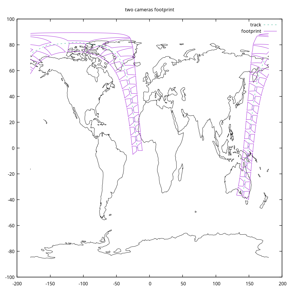
I need to implement the display of shooting on Earth 2 cameras: each of the cameras can be rotated to fixed angles of punging, roll and yawing.

I use this to form one camera with the following code: I would like to turn the direction of the camera - but I rotate the frame. What ways to rotate the camera are possible here and which are more accurate and convenient?

My code: as a result of its execution, the projection display of my camera shifts a little, but I don’t know how to assess whether it’s turned correctly or not.


TopocentricFrame topocentricFrame = new TopocentricFrame(earth, gp_State_Spacacraft), “Camera_1”);

var Rotor = new Rotation(RotationOrder.XYZ, RotationConvention.VECTOR_OPERATOR, FastMath.PI / 6., FastMath.PI / 6.,FastMath.PI / 6.);

Frame myFovFrameRotor = new Frame(topocentricFrame,
                         new Transform(AbsoluteDate.ARBITRARY_EPOCH, 

                                       Rotor),

                                       "myFovFrame");

PolygonalFieldOfView fov = new PolygonalFieldOfView(Vector3D.MINUS_K,
DefiningConeType.INSIDE_CONE_TOUCHING_POLYGON_AT_EDGES_MIDDLE,
Vector3D.MINUS_I,
FastMath.toRadians(angleFOV), 4, 0.0);
Transform topoToBody = myFovFrameRotor.getTransformTo(itrfFrame_for_earth, currentState.getDate());

            Transform topoToBody = topocentricFrame.getTransformTo(itrfFrame_for_earth, currentState.getDate());

List<List> resu = fov.getFootprint(topoToBody, earth, FastMath.toRadians(10));

How do I properly turn my rectangle so that it looks down perpendicular to the direction of flight at an angle of 16 degrees, the zero meridian should be counted in the direction of the lower left point of the rectangle clockwise, the camera angle is 30 degrees? I make different transformations and rotations to the angles of the center and meridian vectors - but as a result, the foot print gives 0.
I reread all the topics that are on the forum - but nothing helps

How do I properly turn my rectangle so that it looks down perpendicular to the direction of flight at an angle of 16 degrees, the zero meridian should be counted in the direction of the lower left point of the rectangle clockwise, the camera angle is 30 degrees? I make different transformations and rotations to the angles of the center and meridian vectors - but as a result, the getFootprint gives 0.
I reread all the topics that are on the forum - but nothing helps

As I understand it, I need to rotate the center 16 degrees and direct the meridian to the lower left corner of the rectangle?

I also used Loffofset - but they show themselves very badly and often object to zero

I need not only to correctly display the camera on the 2D map, but also then determine which regions fall into the visibility of the camera. Therefore, I need to perfectly correctly identify the camera related to the position of the spacecraft

Attitute provider and loffofset also showed bad results - but I would like to set the rectangle correctly - and if it’s can’t resort make to the loffoset

I used it’s: sorry, I manually write code from memory:

double angleCenter= Math.toRadians(16);

Vector3D center = new Vector3D(Math.cos(angleCenter), Math.sin(angleCenter), 0);

Direction of the meridian to the lower left corner:

double vectorMeridian = new Vector3D ( FastMath.cos(90 in rad) * FastMath.cos(45 in rad), FastMath.sin(90 in rad) * FastMath.cos(45 in rad), FastMath.sin(45 in rad)

PolygonalFieldOfView fov = new PolygonalFieldOfView(

center.normalize(),

DefiningConeType.INSIDE_CONE_TOUCHING_POLYGON_AT_EDGES_MIDDLE,

vectorMeridian.normalize(),

FastMath.toRadians(30), 4, 0.0);

But such non-single vectors give zero in getfootprint

I also used frame transformations tied to the state of the spacecraft - but they do not work well and often give zero:

inertToBody = state.getFrame().getTransformTo(earth.getBodyFrame(), state.getDate())
fovToBody = Transform(state.getDate(),
state.toTransform().getInverse(),
inertToBody)
footprint = fov.getFootprint(fovToBody, earth, radians(10.0))

Used AttitudeProvider = new NadirPointing(orbit.getFrame(), earth) and new LofOffset(orbit.getFrame(), LOFType.LVLH, RotationOrder.XYZ, FastMath.toRadians(0), FastMath.toRadians(16), FastMath.toRadians(0)) also give null in getfootprint

Did you look at how the unit tests for PolygonalFieldOfView were implemented?
You can find them in the src/test directory in the source distribution, or look online here. In these tests, the orientation is basically changed using the attitude provider when calling the doTest method. I would suggest to use a LofOffset attitude provider and since the center of your FoV is along -Z, I would suggest using LOFType.VNC as the base orientation to be sure Z points away from Earth. In this case, changing the rotation angle around the Z axis implies setting a non zero third angle when building the LOFOffset.

Thank you for answer

Yes, I see PolygonalFieldOfViewTest and test more variant

I’ll try tomorrow LOFType.VNC

I would like to know about such settings that would rotate my camera and the drawing of the result was correctly and beautifully distributed along the flight route - that is, at an angle, not parallel to the equator.

If you look at this picture, I need to rotate the camera around the OX axis by 16 degrees in both directions. But I’m still looking at one camera, the second one will be the same, but from -16 degrees

Also, the projection should be as if perpendicular to the flight route, the projection of the position of the spacecraft on the ground. But in my calculations, if the camera can be obtained, it is parallel to the equator, and should be perpendicular to the flight route

The photo shows approximately the correct location of the cameras - but I did it with rotate plus all sorts of angle checks - I want to get it from the position of the spacecraft naturally

If you use an attitude provider based on local orbital frame, it will follow the orientation along track, even if you set all offset angles to 0.

In classical Earth observing missions, one often use the YawCompensation atttitude mode, wrapping a NadirPointing. The low level NadirPointing ensures the Z axis is towards local vertical (taking Earth flattening and orbit eccentricity into account, which the LOFOffset mode don’t do), and the wrapping YawCompensation ensures the orientation is always exactly along relative velocity of spacecraft and Earth, i.e. it also compensates the velocity of ground points, which is greater at equator and smaller at high latitudes. It does this automatically.

So for more accurate results, YawCompensation + NadirPointing is better than my former suggestion of LOFOffset

@luc I need to determine the FOV very well - because later I will write FootprintOverlapDetector - and he understands only the input of FOV (without my modification camera in my code program with Rotate Hipparchus etc) - if I somehow inclined it somewhere in the propagator - this will not be taken into account in FootprintOverlapDetector. FootprintOverlapDetector will take into account pure FOV - that’s exactly the FOV I need to tilt.

Ideally, I would like to tilt the center and meridian into the FOV - but I tested it and it doesn’t always work.

But if you even use a loffset, how do you include the loffset Pitch, roll and yaw in FootprintOverlapDetector?

Thank you, I’ll try it again - I’ll let you know about the results

The FootprintOverlapDetector also takes into account the attitude that is used by the propagator.

So if you set up the attitude provider to define what we could roughly call the center line of the track and set up the orientations for the FoV to consider fixed roll/pitch/yaw with respect to this center line, then everything will work. The propagator will compute the attitude at each step, and the detectors will compute the orientations of the FoV with respect to this attitude and then project everything to ground.

Thank you, that’s good, I wasn’t sure about that.

I need to make the code work with it: it doesn’t work for me yet, but it works if you replace the fov with a circle with Vector3D.PLUS_K:

CircularFieldOfView(Vector3D.PLUS_K, FastMath.toRadians(3.0), 0.0),

But I need a rectangle:

propagator.setAttitudeProvider(new NadirPointing(orbit.getFrame(), earth));


PolygonalFieldOfView fov = new PolygonalFieldOfView(Vector3D.MINUS_K,
DefiningConeType.INSIDE_CONE_TOUCHING_POLYGON_AT_EDGES_MIDDLE,
Vector3D.MINUS_I,
FastMath.toRadians(angleFOV), 4, 0.0);

inertToBody = state.getFrame().getTransformTo(earth.getBodyFrame(), state.getDate())
fovToBody = Transform(state.getDate(),
state.toTransform().getInverse(),
inertToBody)
footprint = fov.getFootprint(fovToBody, earth, radians(10.0))

Here is what I could came up to implement your problem.

I have taken provisions for roll, pitch and yaw offsets for the cameras. The image below uses 0° for roll and pitch for a better display, but you can of course play with the angles to see how they change the orientations of the cameras. In the code, the roll angle is reversed on the left and right cameras, so the display remains symmetrical, but I don’t know if it is what you need, your mileage may vary.

This example program needs gnuplot to be installed in order to generate the display, as well as the world_110m.txt that can be retrieved from gnuplotting site. You may need to adapt it for your plotter of choice.
TwoOffsetCameras.java (11.8 KB)

1 Like

@luc Thank you very much - this is the best solution for me :sparkles:

That’s what I can do - that’s what I expect. The only thing I get lines and areas on the map when crossing the boundaries of the map from -179 to +179 in longitude (the same will be in latitude if the camera drawing crosses the top and bottom of the map).


Is there no normalization of longitude and latitude during the formation of the footprint? Checks for (-179 - (+179)) < -358 and (+179 - (-179)) > 358 do not work in general if you go through all the longitudes - this method spoils areas elsewhere in the map

Maybe there’s something for that?

Regarding the same question:

When we determine our rectangle, we determine the direction of the meridian and I tried to use it like this: According to the figure, turns along the X-axis by 30 degrees and bringing the vector to the lower left corner - for example, rotating along the Y-axis by an angle of 32/2:

var firstMeridianRotor = new Rotation(RotationOrder.ZYX, RotationConvention.FRAME_TRANSFORM, 0, Math.toRadians(32/2), Math.toRadians(30));

And used it’s for my meridian on polygons (too from Vector3D.PLUS_K:


PolygonalFieldOfView rightFov = new PolygonalFieldOfView(rightOrientation.applyTo(Vector3D.PLUS_K),
                                                                 DefiningConeType.INSIDE_CONE_TOUCHING_POLYGON_AT_EDGES_MIDDLE,
                                                                 firstMeridianRotor.applyTo(Vector3D.PLUS_K),
                                                                 fovSize, 4, 0);

I thought that if I defined our initial meridian (zero or prime meridian) as a vector from the top of the camera to the lower left point of the rectangle, I may get longitude values in a getfootprint that will NOT give parasitic lines and parasitic sets outside the rectangle on the map.

But it didn’t help: the essence I wanted to do it as in the figure - to determine the zero meridian - the edge from the top of the camera to the lower left point: the X-axis looks directly at us: maybe to determine the zero meridian you need to make a simpler turn, maybe set this meridian not FRAME_TRANSFORM, а VECTOR_OPERATOR?

In this case, 32/2 degree will be equal to the same 30 degrees as it is a square

The simplest thing to do for dealing with jumps at anti-meridian is copy what I did in the program: always keep previous point before drawing a point and check if the gap is greater than π, which indicates a jump.

In this case, depending on what you want to do, there are two options:

  • if you want to compute something like a mean value from sample points, or a slope using some kind of finite differences, then you remove the jump by adding/removing 2π
  • if you want to plot something on a map that is a,nyways clipped to -π; +π, then you insert a line break

I chose the second option when plotting the image and as you see this avoids the long horizontal lines.

In order to rotate you sketch around the Z axis, you can use the yaw angle in the code I wrote, this would allow to get whatever direction you want aligned with X axis: either on vertex, or the center between to vertices if you set up a π/4 rotation for example.

Beware that I just put a rotation using Cardan angles which are 3 successive rotations (not simultaneous ones) and in this case I selected the order ZYX. Maybe in your case you should create differently the rotation from spacecraft frame (the one that is the output of the attitude provider and that is aligned with track) and the field of view frame (the one that defines the vertices and edges of the fov). This really depends on the design of your instrument, you need to delve more deeply by yourself into this design in order to model accurately the instrument and then get the correct footprint.

1 Like

Hello, I have learned a lot from your various posts. Thank you for that.
I have a question while learning, similar to this post. How can I achieve the leftOrientation effect using DoubleDihedraFieldOfView?
Here is your code:
PolygonalFieldOfView leftFov = new PolygonalFieldOfView(leftOrientation.applyTo(Vector3D.PLUS_K),
DefiningConeType.INSIDE_CONE_TOUCHING_POLYGON_AT_EDGES_MIDDLE,
leftOrientation.applyTo(Vector3D.PLUS_I),
fovSize, 4, 0);
Thanks!

You can try to apply leftOrientation to all the vector that are used as contruction parameters for DoubleDihedraFieldOfView.