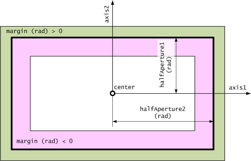
In my code I use (three) direction cosines for each axis with respect to the satellite body-fixed fame. However, from the results I generate I think that it is not the right setting. I tried to find the definition of the axis parameters on my own but I couldn’t. I am including my sketch of the dihedral FoV below.
Can you help?
Thank you and best regards.
Bogdan
Thank you @luc. The changes worked. I have updated the figure.
In your sketch halfAperture1 and halfAperture2 are exchanged.
The angle halfAperture1 is counted “around” axis1.
So if for example you have center = X, axis1 = Y, axis2 = Z, then halfAperture1 is an angle counted around Y.
I.E if halfAperture1 is a tiny angle, the dihedra 1 will be a thin spindle-shaped strip along the (-Y,+X,+Y) half plane. The value of halfAperture1 correspond to how wide the strip is. If halfAperture1 is PI/2, then the strips
enlarges a lot up to correspond to the half sphere on the +X side.
I have an additional question regarding the FieldOfView class. I am trying to set up a sensor placed somewhere on a spacecraft with the goal of simulating proximity operations. I defined a sensor frame as a child of the spacecraft body frame and have calculated the state vectors of other spacecraft in the sensor frame but I would like to detect when they are inside the FoV of the sensor.
In the current implementation the origin of the sensor frame, hence the center of the spherical lune of a dihedral FoV, is at the center of mass of the spacecraft. While this works well on a sensor that looks at Earth it is a less-than-desirable constraint for proximity operations.
I have tried to program a workaround using multiple intersecting FoVs but it doesn’t work well. Is there a workaround that someone has tried already?
To summarize, I am looking for a way to define a FoV with origin shifted from the center of mass of the spacecraft and use that FoV with a FieldOfViewDetector method.
In order to have parallax computed properly, you will need to set up a dedicated detector : FieldOfViewDetectorWithParallax that extends FieldOfViewDetector. This detector
will have an additional field scToSensor (a Transform instance) to store the offset and
rotation between the center of the sensor and the spacecraft center of mass.
Then, you will override the g function as follows
    @Override
    public double g(final SpacecraftState s) {

        // get line of sight in spacecraft frame
        final Vector3D targetPosInert =
                targetPVProvider.getPVCoordinates(s.getDate(), s.getFrame()).getPosition();
        final Transform inertToSensor = new Transform(s.getDate(), s.toTransform(),  scToSensor);
        final Vector3D   lineOfSightSensor = inertToSensor.transformPosition(targetPosInert);

        return fov.offsetFromBoundary(lineOfSightSC);

    }
The scToSensor could also be stored in the FieldOfView class directly, but this would change
the construction API and the semantics of the parameter to method offsetFromBoundary. The
current meaning is to just consider the direction, ignoring the magnitude, but if scToSensor is
introduced, we need to tell the vector is a position in meters with respect to the spacecraft
frame.
Bonne Annee 2019! @luc, thank you for your suggestion. Only now I have time to get back to these simulations. I will work on the specialized detector class and post updates.
Do you think it might be worthwhile to include a detector class with parallax in future releases of Orekit? I don’t know if the request period is still open but I can put it in.
Yes, it may be worthwhile to add this.
We are now finishing the 9.3 release (I am late on this), so it would be bet to include it in the next
version, which will almost certainly be a major one: 10.0. As we can change API at major releases,
it would probably be better to update the FieldOfView/FieldOfViewDetector class themselves rather
than create a new detector.
Thank you for the answers in regarding this topic.
I have a follow-up question regarding the axis when defining a FieldOfView for a spacecraft. I am trying to define an aperture around the velocity axis and I am now wondering if It is supposed to correspond to the X axis (Vector3D.PLUS_I) or the Y-axis (Vector3D.PLUS_I) when using a NadirPointing attitude.
Edit: I have run a comparison with STK and it looks like the X-axis corresponds to the direction of the velocity vector.
Thank for very much in advance for any clarification.
Regards
The field of view is defined with respect to the spacecraft frame, but the orientation of the spacecraft frame with respect to velocity vector depends on the attitude you select.
You can for example add this to your propagator settings in order to have spacecraft frame
perfectly aligned with a selected Local Orbital Frame:
As the VNC Local Orbital Frame has its X axis along velocity, using X as the central axis of your
field of view should work for your need. There are other Local Orbital Frames, and you can also set up angular offsets with respect to the LOF (hence the name LofOffset for the attitude provider).
Note that the default attitude providers for propagators is EME2000 aligned, which is not waht you want.
Hello Luc,
Thank you for your answer. What happens when you set the attitude to NadirPointing then? With some comparison check I did with STK X looked like it was toward velocity as well.
It is only roughly towards velocity as it depends on orbital eccentricity and Earth flattening.
The nadir pointing attitude is defined to have the spacecraft +Z axis exactly in nadir direction (which takes into account Earth flattening) and to have the velocity in the (+Z, +X, -Z) half plane. If Earth were perfectly spherical and orbit perfectly circular, then +Z would be exactly towards Earth center and +X would be exactly towards +X. Earth flattening and orbital eccentricities introduce small angular deviations, but this may be what you need, it depends on the real controlled attitude of your spacecraft.
I am using a circular orbit at the moment that is propagated using a NumericalPropagator with only the J2 effect. (using the HolmesFeatherStone force model with coefficient provider set to n=2, m=0)
Is your recommendation to set the attitude using a LOFOffset rather than using the NadirPointing attitude to get Z in the Nadir direction and X in the velocity direction?
if you really need Z to be on Nadir, then NadirPointing is what you need. If you really need X to be on velocity, then LOFOffset (with the VNC choice of LOF type) is what you need. What I say is that as with real Earth and real orbit, nadir and velocity are not orthogonal to each other, then you cannot have at the same time Z on nadir and X on velocity.
What NadirPointing does is put the priority on Z alignment on nadir, and then it attempts to put X as close as possible to velocity. What LOFOffset (with the VNC choice of LOF type) does is put priority on X alignment to velocity, and Y on orbital momentum, hence Z will be almost opposite to nadir.
No, BodyCenterPointing is equivalent to VVLH (I did not check numerically, though, it would be interesting to do).
Nadir is not in the direction of Earth center, it is aligned with the local vertical. As Earth is flattened at poles, local vertical does not contains Earth center except for points at either pole or at equator. The maximum difference between nadir and Earth center direction is about 0.3° if I remember correctly.